
DIY Smart Lock with Arduino and RFID
- 🚀 Project intro
- Features
- Requirements
- 📁 Project structure
- How to setup the project
- Troubleshooting
- 📄 License
In this project, I have used an RFID reader (MFRC522), Arduino microcontroller (Mega 2560), Arduino programming language and other components to create an RFID-based smart lock. This lock is a small version of an automated RFID-based smart lock, an important component of an automated home.
| Feature | Status | Description |
|---|---|---|
| RFID access control | ✅ Current | Uses the MFRC522 module to read authorized RFID tags and grant access. |
| Master card programming | ✅ Current | Lets you define a master card to add or remove user cards. |
| EEPROM storage | ✅ Current | Saves approved RFID IDs in non-volatile memory so access records remain after power loss. |
| LED status feedback | ✅ Current | Uses red, green, and blue LEDs to indicate access, denial, and programming mode. |
| Solenoid lock control | ✅ Current | Activates a relay/MOSFET circuit to unlock the door for a set duration. |
| Wipe/reset mode | ✅ Current | Supports a wipe button to clear stored records and reset the system. |
- Arduino. I've used a Mega 2560, though any Arduino board or clone will suffice.
- 3 x 220 ohm resistors
- 1 x 10k ohm resistor
- Logic-level N channel MOSFET
- MFRC522 module with at least two cards
- Red, blue, and green LEDs
- 12v Solenoid ($2)
- 12v power supply
- Breadboard and hook up wires
- Arduino IDE
- MFRC522 library
- SPI and EEPROM libraries (already included with the Arduino core)
- Serial Monitor set to 9600 baud for debugging and setup
Microcontroller-based-DIY-Smart-Lock/
├── CSE323_PROJECT/
│   └── CSE323_PROJECT.ino
├── HARDWARE SETUP/
│   └── CSE323 Project Hardware Circuit setup.pdf
├── Delay-Timer-Circuit-using-IRFZ44N.jpg
├── Introduction-to-IRFZ44N_3.png.png
├── LICENSE
├── pinout-Arduino-Mega2560__1.png
├── pinout-Arduino-Mega2560__2.png
├── ProjectCode.zip
└── README.mdThe following Arduino Mega 2560 pin diagram shows the main board connections and pin layout used during the hardware setup.

Use the files in this repository in this order:
- Open the hardware setup guide in
HARDWARE SETUP/CSE323 Project Hardware Circuit setup.pdfto wire the Arduino Mega 2560, MFRC522 reader, LEDs, relay/MOSFET, and 12V solenoid correctly. - Open
CSE323_PROJECT/CSE323_PROJECT.inoin the Arduino IDE and make sure the required libraries are available:SPI.h,EEPROM.h, andMFRC522.h. - Upload the sketch to the Arduino Mega 2560 using the pin mapping defined in the code:
- MFRC522 RST → pin 5
- MFRC522 SDA/SS → pin 53
- SPI MOSI → pin 51
- SPI MISO → pin 50
- SPI SCK → pin 52
- LEDs → pins 6, 8, and 10
- Relay/MOSFET control → pin 11
- Wipe button → pin 33
- Power the circuit with the 12V supply and then open the Serial Monitor at 9600 baud to follow the setup process.
- Scan a tag to define it as the master card, then use other RFID cards to grant or deny access. Press and hold the wipe button to clear stored RFID records if needed.
This setup is based on the main sketch, the hardware circuit guide, and the Arduino Mega pin diagram files included in the project folder.
- The Arduino boots and initializes the SPI communication with the MFRC522 reader.
- The system waits for an RFID tag to be scanned.
- If the scanned card matches the stored master card, the device enters programming mode.
- In programming mode, new cards can be added or removed from EEPROM memory.
- In normal mode, authorized tags unlock the solenoid for a short time, while unknown tags trigger the denied signal.
- The wipe button can erase the stored access records when you want to reset the system.
- If the MFRC522 reader is not detected, check the SPI wiring and ensure the correct SS/RST pins are connected.
- If the relay or solenoid does not respond, verify the MOSFET/relay driver circuit and the 12V supply.
- If the serial monitor shows no output, confirm that the board is connected and the baud rate is set to 9600.
- If cards are not being recognized, re-scan the master card and confirm the RFID library is installed correctly.
Watch the project demonstration video below to see the smart lock in action.
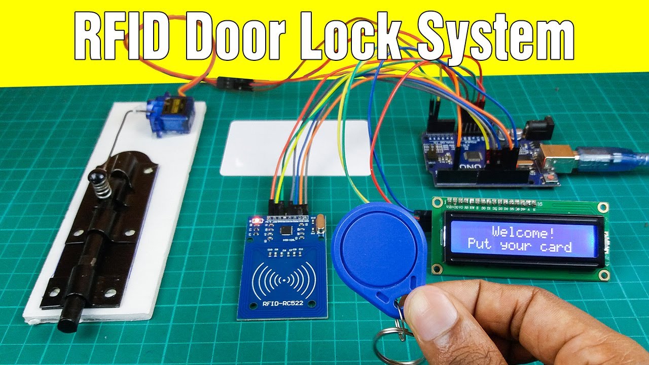
Click the image above to open the YouTube video in a new tab.
This project is licensed under the MIT License. See the LICENSE file for details.